
◷ Reading Time: 10 minutes
To Start building diagram documents let’s set up a project and add a new Activity Flow.
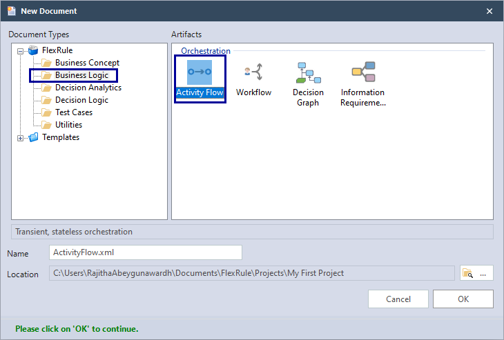
This is not specific for that logic document type and the same techniques are also applied for Decision Graphs and Information Requirements Diagrams.
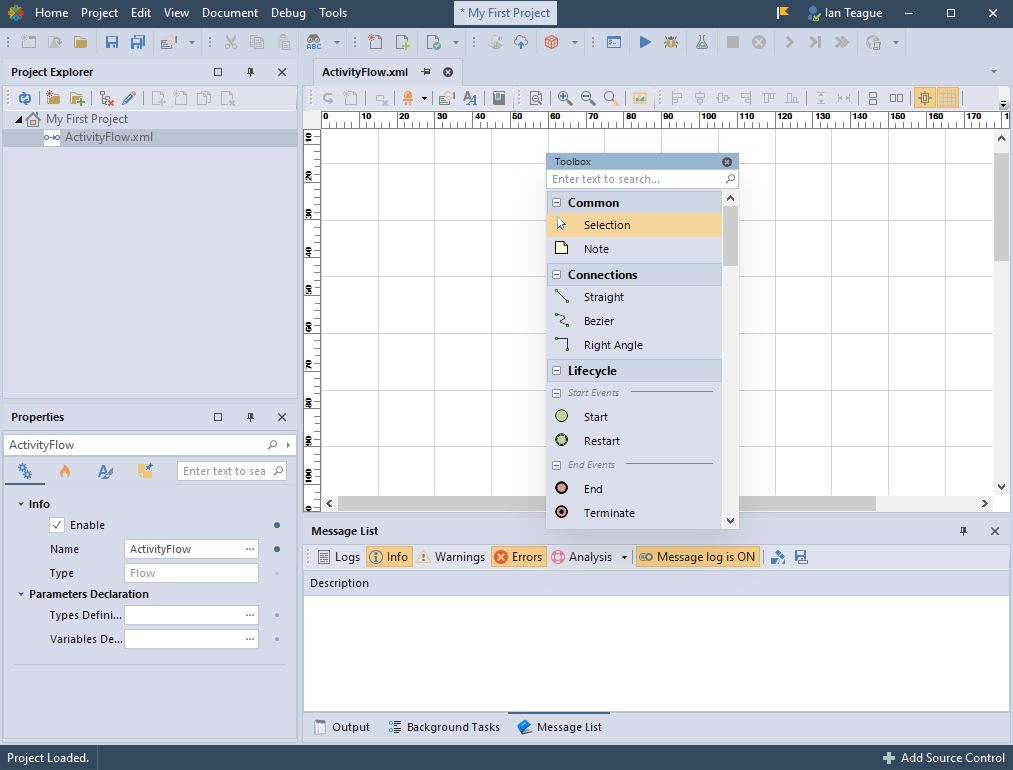
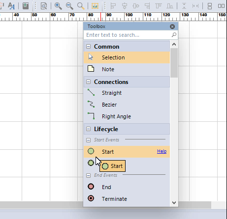
Using drag and drop techniques, add three nodes to the Diagram:
- Start
- Action
- End
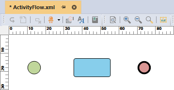
And build the following Diagram model:
Updating Nodes
Hover and Select Nodes
When you hover (going over) any node on the diagram, you will see that a couple of small red circles will appear on that element.

Multiple Nodes Selection
To select multiple nodes, you can just press your left mouse button on an empty space, hold the mouse button down and drag your mouse until you cover all the nodes you want to select by the transparent blue selection guild

and then release your mouse button

You will see multiple selected items having small white and gray rectangles around them.
Move Nodes
To move one or more nodes in a Diagram, you need to select them and then move your mouse to the center of a node over the white or gray rectangle. Then hold down your left mouse button and drag it.

After you have positioned the node in the new location, release your mouse button. If you select multiple nodes, you can move them all together.
Grid and Target alignment
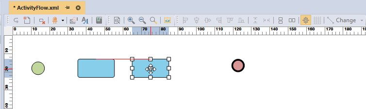
Each visual logic documents drawing canvas includes a grid that allows the user to align nodes and elements to the grid so creating clean and ordered documents.
Addition to the grid is a Target alignment option where red indicator lines show the alignment of a node with others as the user moves the node around the canvas. This is helpful to also to create clean and ordered documents.
Resize Nodes
For resizing a node, you do the same, but instead of pointing your mouse at the center of the node, you go over the corner rectangles. Then you press the left mouse button, hold and drag it.

And when it is the size you want, release your mouse button. You can resize nodes in any direction you want by using all the edges controlling the white rectangles.
Adding Text
You can add display text to nodes on a diagram. To add a text you need to hover on the node and then double click on that node. When you do that, a text editor will appear.

And once you have finished editing the text, click somewhere outside of that text editor.

Please note that in the in-place text editor ‘Enter’ goes to the next line, which is useful if you need to add multiple lines of text.
Resize and Relocate Text
From version 8 of FlexRule Designer, you will have the ability to move and resize the nodes’ labels.
For example, below is an Activity node.

If you click on the node, you will see the anchor points to resize or move.

If you click on the node while pressing the ALT button on the keyboard you will see the anchor points around the labels.

It gives you the ability to resize and move the labels.

Oversized Model
If you have an oversized model that does not fit into your screen, the scroll bars will let you scroll to the model and view different parts of it.

You also can use tools for an oversized model that lets you manage a big model.
Overview: This loads the smaller version of the diagram in a separate window.

Then you can select what part of the diagram comes to the current view by moving the active area on the overview window.
Zooms:
 The Plus magnifying glass zooms the model in.
 The minus magnifying glass zooms the model out, so that it will fit on your screen.
 The clear magnifying glass sets the zoom option in the normal view.
Connecting Nodes
To connect nodes, you need to first select the type of connection from your toolbox

and then:

Hover on the source node that you want to connect to a destination node. Please note when a connection is selected in the toolbox, by hovering on a node, your mouse icon becomes like a small hand.

Press the left mouse button and drag it to the other element you want to connect to

And release the mouse button – the connection will be created
Connection Types
You have different types of connection shapes in your toolbox:
- Straight
- Bezier
- Right Angle
And you can change an existing connection to another type. First, you need to:

Select a connection

Click on the Change button on the toolbar.

Press the small arrow-down to open the menu on the toolbar and select the connection type you like. The icon of the button will be changed.

The connection type is changed.