◷ Reading Time: 8 minutes
What is a Decision Requirements Diagram?
Decision Requirements Diagram is an orchestration model that inter-connects decisions such as Decision Tables, reusable sub-DRD, Business Knowledge and other types of decision nodes.
Decision Requirements Diagram can also be created following Decision Model and Notation (DMN), which is an open standard notation for modeling decisions that are based on logic, data, and processes. It was developed by Object Management Group (OMG) in 2014. It provides meta-model, notation, and semantics for decision modeling. This is a complimentary notation to BPMN for modeling operational decisions and business rules.

What is a Decision
A decision is an act of determining an output value, based on a number of input values, using logic defining how the output is determined from the inputs. A decision model is a model in a specific area that defines decision requirements and decision logic.
In DMN, A decision is modeled at two levels:
- Decision Requirement
- Decision Logic
A Decision Requirements Diagram is a high-level model that defines one or more Decision Requirements Diagrams, which makes a Decision Requirement Graph (DRG). At the Decision Logic level, the different details of the implementation of logically related to each node (e.g., Decision) in the DRG is defined. This logic can have any implementation, but as far as DMN is concerned the Decision Table is a standard way of logic implementation.
Sub-Decision Requirements Diagram
The Decision Requirements Diagram allows connecting sub-Decision Requirements Diagrams in the decision hierarchy. This also ensures that the reusable Decision Requirements Diagrams can be connected as necessary without having to duplicate the decisions.
For example, in the following figure, you can see that we have reused the Post-Bureau Affordability graph in both Bureau Strategy Decision and Approval Decision.

Knowledge Source
One of the benefits of modeling in DMN is that, not only can it model the actual decision-making process at different levels, but also that you can model (link) the documentation, references, and authorities around these. The Knowledge Source is for that purpose. Also, it can be used to check the impact of change if these sources are changed.
Decision Logic Level
At this level, the implementation of decisions and business knowledge can be linked to each node at the decision requirement level. These implementations can vary based on your needs, product capabilities, and other factors (e.g., your familiarity with a specific type of logic: Decision Table, Tree, etc.).
Decision Table
In DMN, a Decision Table is a common way to present business knowledge in a tabular form. It has its own characteristics compared to a generic decision table.
Other Logic Types
In FlexRule, we support other types of logic as well as Decision Tables, so you can simply link this logic to business knowledge as the implementation of the logic. This logic is:
- Decision Table (DMN standard method)
- Boxed Expression
- Natural Language
Decision Requirements Diagram Elements
In the table below, all of the elements on a Decision Requirements Diagrams are illustrated:
| Element | Notation | Description |
|---|---|---|
| Decision |  | The act of determining an output from a number of inputs, using decision logic which may reference one or more business knowledge models. |
| Business Knowledge Model |  | A function encapsulating business knowledge, in the form of business rules, decision tables or an analytic model. |
| Knowledge Source |  | The authority for a business knowledge model or decision. |
| Input Data |  | Information used as an input by one or more decisions. It also denotes the parameters of a Business Knowledge Model. |
| Information Requirement |  | Information – input data or decision output – required for a decision. |
| Knowledge Requirement |  | The invocation of a business knowledge model. |
| Authority Requirement |  | Showing the knowledge source of an element or the dependency of a knowledge source on input data. |
To add a new Decision Requirements Diagram,
Document Types --> Business Logic --> Decision Graph

Once you added a term, this will be the window.

Decision Requirements Diagram Properties

- Name: Name of the flow
- Node Type: Type of the node
- Types Definition: List of types and functions
- Variable Definition: Define variables to be used in the flow
- Glossaries: Link Business Glossaries and Business Formulas
- Resources: List of resources to reference
Toolbox
The toolbox has the following items.

Top Menu
At the top menu, you can see the following items.

- Open the related logic document for this node: Open the logic document of a selected node
- Create a logic document for selected node: Create a logic document for a selected node
- Delete item: Delete a selected item
- Highlight the impacts of the selected node: Highlight the impacts of a selected node
- Properties: Properties of the page or a node
- Variable properties: Define/ update/ delete variables
- Compile to execution plan: Shows the XML version of the diagram
- Business Glossary: Link Business glossaries and Business formulas
- Overview of entire model: See the entire model
- Zooming: Zoom in or zoom out
- Export to image: Export the document to an image
- Alignments: Align nodes
- Resize: Resize selected nodes to a single size
- Layout arrangements: Automatically arrange and layout the nodes
- Change connections: Change connection styles to straight/ Bezier or Right Angle
Node/ Connection Properties
If you click on a node/ connection, its property window will appear. The properties vary depending on the node type.
Function Invoke
In DRD you can invoke a function on any decision node. Lets consider the following example.
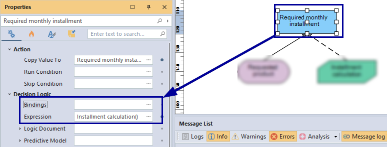
The decision node “Required monthly installment” has a child node(Business Knowledge) called “Installment Calculation,” which is defined as a Function.

Lets see how we can invoke this function in the decision node of “Required Monthly installment”. Functions can have multiple arguments or else without an argument. In this example “Installment Calculation” function has 4 arguments defined. Because of that we need to pass the values to this argument when we invoking the function.
This can be done by defining Binding parameters. Name of the binding parameter will be the argument name defined in the function. Value is what you want to pass into the function. Also, the Expression will be the name of the function. (In this example: “Installment calculation”- name of the Business Knowledge)

If it is a no argument function, to invoke the function we have to use empty paranthesis ( ) in front of the function name.